Using InfoWorks ICM for micro scale modelling of retrofitted SuDS
Katie Powell, Richard Allitt Associates Ltd and Alex Grist, Innovyze.
When a project for retrofitting SuDS is identified, modelling your options can be beneficial when there are complex situations to be addressed or there is some uncertainty about the outcome. Modelling in these situations should enable the risks to be better managed and the most cost effective solution to be identified.
However, modelling SuDS can be complicated. As a modeller I can attest that it’s fairly simple to model a large underground storage tank but modelling something small and complex that will accept flows from overland runoff is entirely different. This is especially true when retrofitting SuDS as you usually have a restricted area in which to work.
There is currently no industry prescribed method of modelling SuDS in 2D. Most modelling software (like InfoWorks ICM) have a number of features designed for modelling SuDS such as ponds, permeable pavements and swales. However, these are all 1D features and while they can accept flows from sewers and watercourses, you cannot use them to show the passage of overland flow. To visualise overland flow and make sure you’re siting your SuDS device in the correct location, you really need to be modelling in 2D.
To show you what I’m talking about let’s look at an example where we undertook some modelling work for a Water and Sewerage Company (WaSC) client who were looking to restrict the volume of surface water runoff from a highway discharging into an overloaded combined sewer.

This site is on a road on a steep hill. The road is very wide, and part of the road next to a junction is hashed to prevent parking, ensuring clear views out of the junction.
The most appropriate option for this site was a rain garden in the hashed area, detailed below:
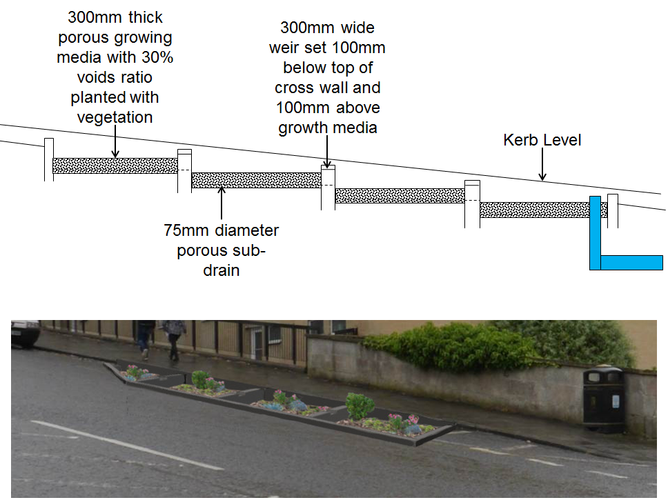
Key aspects of the design are the cascading compartments required due to the steepness of the road; surrounding kerb to reduce the risk of cars driving into the rain garden; low level planting to avoid obscuring views around the junction; walls to allow storage in each compartment; weir walls to allow each compartment to fill; and porous growth media to allow flows to infiltrate into the soil below.
How could we ensure that these were appropriate for the site in question and would provide the required performance? For this we need to model the SuDS in 2D and connect them into the 1D sewer system. This was undertaken using InfoWorks ICM and the modelled output is shown below.
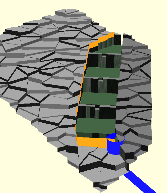
To create the model, we need to utilise multiple 2D modelling structures:
- Mesh zones are required to model the compartments, walls and weirs.
- Mesh zones are crucial for micro-modelling. They allow the user to enhance the detail within an area and adjust the topography.
- Each compartment has two mesh zones, one covering 70% of the compartment set at the level of the top of the growth media and another covering 30% of the compartment set 300mm lower to represent the storage volume provided by the growth media.
- Infiltration zones are required for modelling compartments. Their parameters represent the underlying soil type and how quickly flows infiltrate out of the compartment.
- The road gully at the bottom of the rain garden is modelled as a 2D node. Flows in the rain garden can enter the 1D sewer network via this node. This has to be located within its own mesh zone raised above the lowered 30% of the compartment, to ensure the full storage capacity of the compartment is utilised.
- The kerb around the rain garden is modelled as a ‘base linear structure’ (effectively a wall) raised 200mm above DTM.
Playback of the simulations run using this model demonstrated the compartments filling individually, spilling over the weir walls and building up to the level of the cross wall. It also shows two compartments draining down as infiltration occurs.
Results from the simulations enabled us to ensure that the SuDS was performing as required, reducing the flow into the sewer network and mitigating the impact on the downstream system.
Modelling has multiple benefits:
- Simulations show how long your SuDS should attenuate flows for
- Enables the SuDS to be appropriately sized for treating the ‘first flush’ of pollutants
- Helps visualise flow paths through areas and your SuDS
- Allows you to plan for exceedance
- In this example modelling enabled the client to adopt the best solution and choose the most appropriate location for siting the rain garden.
In conclusion it is feasible to model retrofitted SuDS but for examples such as this micro-scale 2D modelling has multiple benefits and provides a cost effective, appropriate solution. Whilst the set-up of these models can initially be daunting, it is feasible to model these structures and obtain all the benefits that come with being able to test and model the complex interactions of SuDS structures. Having created a model, we can use this to analyse our SuDS structure performance when subject to a variety of events and conditions, something not easily possible with simple hand calculation, giving improved confidence and thus, encourage acceptance in the use of SuDS features. In my opinion the benefits far outweigh the complexities of this type of modelling.
To put it simply modelling allowed us to remove the guess work.